Hardware Simulation

Every logical circuit can be described with a Visual Prolog predicate, where the predicate indicates the relationship between the signals on the input and output terminals of the circuit. The fundamental circuits are described by giving a table of corresponding truth values (see the and_, or_, and not_ predicates in Program 4).

Fundamental circuits can be described by indicating the relationships between the internal connections, as well as the terminals. To see how this works, construct an exclusive OR circuit from AND, OR, and NOT circuits, and then check its operation with a Visual Prolog program. The circuit is shown in Figure 16.3.
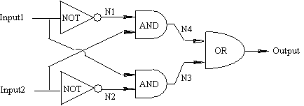
Figure 16.3: Fundamental XOR Circuit

In Program 4, this network is described by the xor predicate.

/* Program ch16e04.pro */


PREDICATES

    nondeterm not_(D,D)

    and_(D,D,D)

    or_(D,D,D)

    nondeterm xor(D,D,D)


CLAUSES

    not_(1,0).      not_(0,1).

    and_(0,0,0).    and_(0,1,0).

    and_(1,0,0).    and_(1,1,1).

    or_(0,0,0).     or_(0,1,1).

    or_(1,0,1).     or_(1,1,1).


    xor(Input1,Input2,Output):-

        not_(Input1,N1),

        not_(Input2,N2),

        and_(Input1,N2,N3),

        and_(Input2,N1,N4),

        or_(N3,N4,Output).

Given the following goal in interactive mode:

    xor(Input1, Input2, Output).

this program yields the following result:

    Input1=1, Input2=1, Output=0
    Input1=1, Input2=0, Output=1
    Input1=0, Input2=1, Output=1
    Input1=0, Input2=0, Output=0
    4 Solutions

Interpreting this result as a truth table, you can see that the circuit does indeed perform as expected.